Large Diameter DN2000 Water Butterfly Valves For Oil , Gas , Acid
Water Butterfly Valves Description
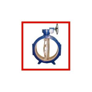
The valve mainly composed of valve body, valve plate, valve shaft, valve seal and drive.
Widely used in water plant, power plants, steel mills, paper making, chemical industry, textile, food and so on used as water supply and drainage, adjusting flux and intercepting medium on the gas pipeline:
1. This valve adopts the double eccentric structure, Have the close tight sealing function , sealed performance is reliable.
2. Sealed auxiliary adopts stainless steel and nitrile oil resistant rubber matching, which has long service life.
3. Rubber sealing ring can be located in the body, can also be on the disc, applicable to different characteristics of medium, for the user to choose from.
4. Butterfly plate adopts frame structure, high strength, large flow area, small flow resistance.
5. Stoving varnish entirely can effectively prevent rust and can be used in different medium if replace the sealing seat sealing materials.
6. This valve has two-way sealing function, installation is not controlled by the medium flow direction, and is not affected by spatial location, it can be installed in any direction.
Water Butterfly Valves Specifications:
Size: DN50 - 3000
Temperature: -15℃ - 150℃
Pressure: 1.0MPa/1.6MPa
Water Butterfly Valves Features:
⊙ Professional design
When initiating the rotary opening movement the disc is off-seated after only a few
degree of opening movement and there is very little wear and tear between seat ring and disc.
⊙ Combine fastness
Stainless steel seat ring is rolled into the valve body by applying special rolling technology
when DN<1200. Ultrasonic spray applies seal of valve body when DN>1400.
⊙ Excellent corrosion protection
Inside electrostatic epoxy resin power coating or vitreous enamel(upon request), outside electrostatic
epoxy resin power coating.
⊙ Reliable health nature
Epoxy resin power is up to the health standard.
Mail part & material
Body, Disc: GGG50 with internal and external epoxy resin coating
Stems: 1Cr17Ni12Mo2Ti, Stainless steel min.13%Cr
Bushing :Bronze CuAI10Fe3
Seal ring, O-ring: NBR, EPDM or FPM
Main external and connection dimension
1.0MPa mm
|
DN
|
L
|
H1
|
H2
|
H3
|
Flange dimensions comply with DIN 2501
|
|
long type
|
short type
|
O
|
C
|
g
|
f
|
b
|
n-d
|
|
150
|
210
|
140
|
226
|
165
|
|
285
|
240
|
212
|
3
|
19
|
8-23
|
|
200
|
230
|
152
|
255
|
192
|
|
340
|
295
|
268
|
3
|
20
|
8-23
|
|
250
|
250
|
165
|
293
|
227
|
|
395
|
350
|
320
|
3
|
22
|
12-23
|
|
300
|
270
|
178
|
326
|
260
|
|
445
|
400
|
370
|
4
|
24.5
|
12-23
|
|
350
|
290
|
190
|
368
|
314
|
|
505
|
460
|
430
|
4
|
24.5
|
16-23
|
|
400
|
310
|
216
|
423
|
346
|
634
|
565
|
515
|
482
|
4
|
24.5
|
16-28
|
|
450
|
330
|
222
|
455
|
385
|
666
|
615
|
565
|
532
|
4
|
25.5
|
20-28
|
|
500
|
350
|
229
|
506
|
422
|
728
|
670
|
620
|
585
|
4
|
26.5
|
20-28
|
|
600
|
390
|
267
|
568
|
490
|
790
|
780
|
725
|
685
|
5
|
30
|
20-31
|
|
700
|
430
|
292
|
632
|
550
|
854
|
895
|
840
|
800
|
5
|
32.5
|
24-31
|
|
800
|
470
|
318
|
692
|
615
|
924
|
1015
|
950
|
905
|
5
|
35
|
24-34
|
|
900
|
510
|
330
|
815
|
678
|
1098
|
1115
|
1050
|
1005
|
5
|
37.5
|
28-34
|
|
1000
|
550
|
410
|
880
|
743
|
1163
|
1230
|
1160
|
1110
|
5
|
40
|
28-37
|
|
1200
|
630
|
470
|
1024
|
860
|
1307
|
1455
|
1380
|
1330
|
5
|
45
|
32-40
|
|
1400
|
710
|
530
|
1210
|
1010
|
1350
|
1675
|
1590
|
1535
|
5
|
46
|
36-43
|
|
1600
|
790
|
600
|
1340
|
1140
|
1480
|
1915
|
1820
|
1760
|
5
|
49
|
40-49
|
|
1800
|
870
|
670
|
1460
|
1360
|
1640
|
2115
|
2020
|
1960
|
5
|
52
|
44-49
|
|
2000
|
950
|
760
|
1660
|
1485
|
1800
|
2325
|
2230
|
2170
|
5
|
55
|
48-49
|
1.6MPa mm
|
DN
|
L
|
H1
|
H2
|
H3
|
Flange dimensions comply with DIN 2501
|
|
long type
|
short type
|
O
|
C
|
g
|
f
|
b
|
n-d
|
|
150
|
210
|
140
|
226
|
165
|
|
285
|
240
|
212
|
3
|
19
|
8-23
|
|
200
|
230
|
152
|
255
|
192
|
|
340
|
295
|
268
|
3
|
20
|
12-23
|
|
250
|
250
|
165
|
293
|
227
|
|
405
|
355
|
320
|
3
|
22
|
12-28
|
|
300
|
270
|
178
|
326
|
260
|
|
460
|
410
|
378
|
4
|
24.5
|
12-28
|
|
350
|
290
|
190
|
368
|
314
|
|
520
|
470
|
438
|
4
|
26.5
|
16-28
|
|
400
|
310
|
216
|
423
|
346
|
634
|
580
|
525
|
490
|
4
|
28
|
16-31
|
|
450
|
330
|
222
|
455
|
385
|
666
|
640
|
585
|
550
|
4
|
30
|
20-31
|
|
500
|
350
|
229
|
506
|
422
|
728
|
715
|
650
|
610
|
4
|
31.5
|
20-34
|
|
600
|
390
|
267
|
568
|
490
|
790
|
840
|
770
|
725
|
5
|
36
|
20-37
|
|
700
|
430
|
292
|
632
|
550
|
854
|
910
|
840
|
795
|
5
|
39.5
|
24-37
|
|
800
|
470
|
318
|
692
|
615
|
924
|
1025
|
950
|
900
|
5
|
43
|
24-40
|
|
900
|
510
|
330
|
815
|
678
|
1098
|
1125
|
1050
|
1000
|
5
|
46.5
|
28-40
|
|
1000
|
550
|
410
|
880
|
743
|
1163
|
1255
|
1170
|
1115
|
5
|
50
|
28-43
|
|
1200
|
630
|
470
|
1024
|
860
|
1307
|
1485
|
1390
|
1330
|
5
|
57
|
32-49
|
|
1400
|
710
|
530
|
1210
|
1010
|
1350
|
1685
|
1590
|
1530
|
5
|
60
|
36-49
|
|
1600
|
790
|
600
|
1340
|
1140
|
1480
|
1930
|
1820
|
1750
|
5
|
65
|
40-56
|
2.5MPa mm
|
DN
|
L
|
H1
|
H2
|
H3
|
Flange dimensions comply with DIN 2501
|
|
long type
|
short type
|
O
|
C
|
g
|
f
|
b
|
n-d
|
|
150
|
210
|
140
|
226
|
165
|
|
300
|
250
|
211
|
3
|
20
|
8-28
|
|
200
|
230
|
152
|
255
|
192
|
|
360
|
310
|
274
|
3
|
22
|
12-28
|
|
250
|
250
|
165
|
293
|
227
|
|
425
|
370
|
330
|
3
|
24.5
|
12-31
|
|
300
|
270
|
178
|
326
|
260
|
|
485
|
430
|
390
|
4
|
27.5
|
16-31
|
|
350
|
290
|
190
|
368
|
314
|
|
555
|
490
|
450
|
4
|
30
|
16-34
|
|
400
|
310
|
216
|
423
|
346
|
634
|
620
|
550
|
500
|
4
|
32
|
16-37
|
|
450
|
330
|
222
|
455
|
385
|
666
|
670
|
600
|
560
|
4
|
34.5
|
20-37
|
|
500
|
350
|
229
|
506
|
422
|
728
|
730
|
660
|
610
|
4
|
36.5
|
20-37
|
|
600
|
390
|
267
|
568
|
490
|
790
|
845
|
770
|
720
|
5
|
42
|
20-40
|
|
700
|
430
|
292
|
632
|
550
|
854
|
960
|
875
|
820
|
5
|
46.5
|
24-43
|
|
800
|
470
|
318
|
692
|
615
|
924
|
1085
|
990
|
930
|
5
|
51
|
24-49
|
|
900
|
510
|
330
|
815
|
678
|
1098
|
1185
|
1090
|
1028
|
5
|
55.5
|
28-49
|
|
1000
|
550
|
410
|
880
|
743
|
1163
|
|
|
|
5
|
|
|
|
1200
|
630
|
470
|
1024
|
860
|
1307
|
|
|
|
5
|
|
|
|
1400
|
710
|
530
|
1210
|
1010
|
1350
|
|
|
|
5
|
|
|
|
1600
|
790
|
600
|
1340
|
1140
|
1480
|
|
|
|
5
|
|
|
1. BRIEF INTRODUCTION:
The butterfly valve is operated by the disc rotating form 0° to 90°, can be applied to cut off or regulate
the flow of medium.
The valve can be actuated by operating lever, handle wheel electric actuator or pneumatic actuator.
Widely used for potable water supply, waste water treatment, electric power plant, gas supply,
warm-air system, smelting plant, ship building, textile, petroleum, chemistry, or other light industries.
2. Specification
|
name
|
Butterfly Valve
|
|
Item No
|
D373H-10K
|
|
DN(mm)
|
DN50~DN3000
|
|
pressure(Mpa)
|
1.0
|
|
Test pressure
(Mpa)
|
Seal test
|
1.1
|
|
Body test
|
1.5
|
|
temperature
|
≤350℃
|
|
medium
|
Water, sewage, sea water, hot water etc.,
|
3. FEATURES
⊙ EPDM seated, good seal
⊙ Low weight
⊙ Low flow resistance
⊙ Small operation torque
⊙ Easy to install and maintain
⊙ Open-close 90° more smoothly
4. APPLICABLE STANDARDS
1. Design according : API 609
2. Test standard according: JIS B2003
3. Connect flange standard according: JIS B2212
4. Face to face standard according: JIS B2002
5. Item Name of part Material Spec
|
NO
|
Part name
|
Material
|
|
1
|
Body
|
SS304
|
|
2
|
Gear box
|
Assembly
|
|
3
|
Disc
|
SS304
|
|
4
|
Stem
|
SS416
|
|
5
|
Seal ring
|
316+Graphite
|
|
6
|
packing
|
Graphite
|
6. Operation:
6.1. The two pipe flange should be smooth.
6.2. Put the butterfly valve in the pipe line, fixed the orientation hole first.
7. Delivery:
When delivery or store the butterfly valve, should keep in dry and cool environment.
8. Note:
8.1. Pipe flange should same as the butterfly valve flange.
8.2. Check the valve before installed, the environment should correspond to the butterfly valve
specification.
8.3. Before open butterfly valve, checking the disc without dirt.
8.4. The disc must be shut off place when installed.
8.5. Adjusting the pipe connect before installed.
8.6. The connect flange should be parallel.
8.7. After installed, the pressure test disc should be open place.
8.8. If the butterfly can not natural open or close, please kindly check it careful, can not strike, tamp or
use extension lever.
8.9. When maintenance or operation, must check the stem, lever, gear box or actuator have correctly
connect. Otherwise the stem will be push by pipe pressure.